


|
|
|
|
I. Bode plots [
Gain and phase margin |
Bandwidth frequency |
Closed loop response ]
II. The Nyquist diagram [ Closed loop stability | Gain margin | Phase margin ]
Key matlab commands used in these tutorial are
bode,
nyquist,
nyquist1,
lnyquist1,
margin,
lsim,
step, and
cloop
The frequency response method may be less intuitive than other methods you have studied previously. However, it has certain advantages, especially in real-life situations such as modeling transfer functions from physical data.
The frequency response of a system can be viewed two different ways: via the Bode plot or via the Nyquist diagram. Both methods display the same information; the difference lies in the way the information is presented. We will study both methods in this tutorial.
The frequency response is a representation of the system's response to sinusoidal inputs at varying frequencies. The output of a linear system to a sinusoidal input is a sinusoid of the same frequency but with a different magnitude and phase. The frequency response is defined as the magnitude and phase differences between the input and output sinusoids. In this tutorial, we will see how we can use the open-loop frequency response of a system to predict its behavior in closed-loop.
To plot the frequency response, we create a vector of frequencies (varying between zero or "DC" and infinity) and compute the value of the plant transfer function at those frequencies. If G(s) is the open loop transfer function of a system and w is the frequency vector, we then plot G(j*w) vs. w. Since G(j*w) is a complex number, we can plot both its magnitude and phase (the Bode plot) or its position in the complex plane (the Nyquist plot). More information is available on plotting the frequency response.
bode(50,[1 9 30 40])displays the Bode plots for the transfer function:
  50
   -----------------------
   s^3 + 9 s^2 + 30 s + 40
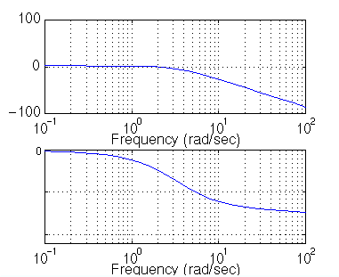
Please note the axes of the figure. The frequency is on a logarithmic scale, the phase is given in degrees, and the magnitude is given as the gain in decibels.
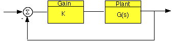
where K is a variable (constant) gain and G(s) is the plant under consideration. The gain margin is defined as the change in open loop gain required to make the system unstable. Systems with greater gain margins can withstand greater changes in system parameters before becoming unstable in closed loop.
The phase margin is defined as the change in open loop phase shift required to make a closed loop system unstable.
The phase margin also measures the system's tolerance to time delay. If there is a time delay greater than 180/Wpc in the loop (where Wpc is the frequency where the phase shift is 180 deg), the system will become unstable in closed loop. The time delay can be thought of as an extra block in the forward path of the block diagram that adds phase to the system but has no effect the gain. That is, a time delay can be represented as a block with magnitude of 1 and phase w*time_delay (in radians/second).
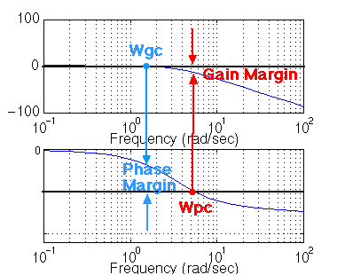
For now, we won't worry about where all this comes from and will concentrate on identifying the gain and phase margins on a Bode plot:
The phase margin is the difference in phase between the phase curve and -180 deg at the point corresponding to the frequency that gives us a gain of 0dB (the gain cross over frequency, Wgc). Likewise, the gain margin is the difference between the magnitude curve and 0dB at the point corresponding to the frequency that gives us a phase of -180 deg (the phase cross over frequency, Wpc).
One nice thing about the phase margin is that you don't need to replot the Bode in order to find the new phase margin when changing the gains. If you recall, adding gain only shifts the magnitude plot up. This is the equivalent of changing the y-axis on the magnitude plot. Finding the phase margin is simply the matter of finding the new cross-over frequency and reading off the phase margin. For example, suppose you entered the command bode(50,[1 9 30 40]). You will get the following bode plot:
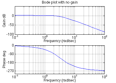
You should see that the phase margin is about 100 degrees. Now suppose you added a gain of 100, by entering the command bode(100*50,[1 9 30 40]). You should get the following plot (note I changed the axis so the scale would be the same as the plot above, your bode plot may not be exactly the same shape, depending on the scale used):
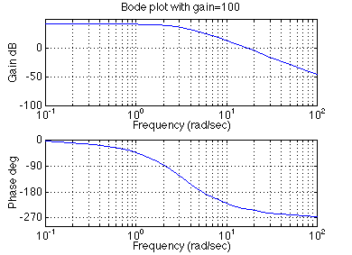
As you can see the phase plot is exactly the same as before, and the magnitude plot is shifted up by 40dB (gain of 100). The phase margin is now about -60 degrees. This same result could be achieved if the y-axis of the magnitude plot was shifted down 40dB. Try this, look at the first Bode plot, find where the curve crosses the -40dB line, and read off the phase margin. It should be about -60 degrees, the same as the second Bode plot.
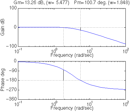
We can find the gain and phase margins for a system directly, by using Matlab. Just enter the margin command. This command returns the gain and phase margins, the gain and phase cross over frequencies, and a graphical representation of these on the Bode plot. Let's check it out:
margin(50,[1 9 30 40])
If you would like to see how the bandwidth of a system can be found mathematically from the closed-loop damping ratio and natural frequency, the relevant equations as well as some plots and Matlab code are given on our Bandwidth Frequency page.
In order to illustrate the importance of the bandwidth frequency, we will show how the output changes with different input frequencies. We will find that sinusoidal inputs with frequency less than Wbw (the bandwidth frequency) are tracked "reasonably well" by the system. Sinusoidal inputs with frequency greater than Wbw are attenuated (in magnitude) by a factor of 0.707 or greater (and are also shifted in phase).
Let's say that we have the following closed-loop transfer function representing a system:
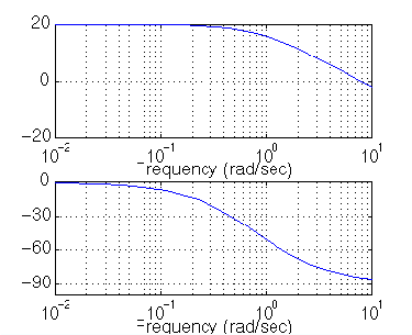
First of all, let's find the bandwidth frequency by looking at the Bode plot:1 --------------- s^2 + 0.5 s + 1
bode (1, [1 0.5 1 ])
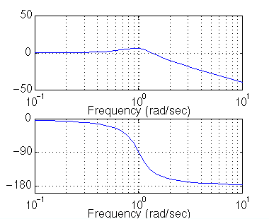
Since this is the closed-loop transfer function, our bandwidth frequency will be the frequency corresponding to a gain of -3 dB. looking at the plot, we find that it is approximately 1.4 rad/s. We can also read off the plot that for an input frequency of 0.3 radians, the output sinusoid should have a magnitude about one and the phase should be shifted by perhaps a few degrees (behind the input). For an input frequency of 3 rad/sec, the output magnitude should be about -20dB (or 1/10 as large as the input) and the phase should be nearly -180 (almost exactly out-of-phase). We can use the lsim command to simulate the response of the system to sinusoidal inputs.
First, consider a sinusoidal input with a frequency lower than Wbw. We must also keep in mind that we want to view the steady state response. Therefore, we will modify the axes in order to see the steady state response clearly (ignoring the transient response).
	w= 0.3;
	num = 1;
	den = [1 0.5 1 ];
	t=0:0.1:100;
	u = sin(w*t);
	[y,x] = lsim(num,den,u,t);
	plot(t,y,t,u)
	axis([50,100,-2,2])
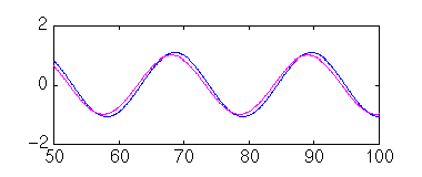
Note that the output (blue) tracks the input (purple) fairly well; it is perhaps a few degrees behind the input as expected.
However, if we set the frequency of the input higher than the bandwidth frequency for the system, we get a very distorted response (with respect to the input):
	w = 3;
	num = 1;
	den = [1 0.5 1 ];
	t=0:0.1:100;
	u = sin(w*t);
	[y,x] = lsim(num,den,u,t);
	plot(t,y,t,u)
	axis([90, 100, -1, 1])
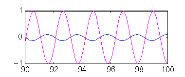
Again, note that the magnitude is about 1/10 that of the input, as predicted, and that it is almost exactly out of phase (180 degrees behind) the input. Feel free to experiment and view the response for several different frequencies w, and see if they match the Bode plot.
Where Gc(s) is the controller and G(s) is:
  10
   ----------
   1.25s + 1
num = 10;
den = [1.25,1];
bode(num, den)
The phase margin for this system is approximately 95 degrees. This corresponds to a damping of PM/100=95/100=0.95. Plugging in this value into the equation relating overshoot and the damping ratio (or consulting a plot of this relation), we find that the damping ratio corresponding to this overshoot is approximately 1%. The system will be close to being overdamped.
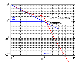
The last major point of interest is steady-state error. The steady-state error can be read directly off the Bode plot as well. The constant (Kp, Kv, or Ka) are located at the intersection of the low frequency asymptote with the w=1 line. Just extend the low frequency line to the w=1 line. The magnitude at this point is the constant. Since the Bode plot of this system is a horizontal line at low frequencies (slope = 0), we know this system is of type zero. Therefore, the intersection is easy to find. The gain is 20dB (magnitude 10). What this means is that the constant for the error function it 10. Click here to see the table of system types and error functions. The steady-state error is 1/(1+Kp)=1/(1+10)=0.091. If our system was type one instead of type zero, the constant for the steady-state error would be found in a manner similar to the following
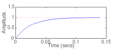
Let's check our predictions by looking at a step response plot. This can be done by adding the following two lines of code into the Matlab command window.
[numc,denc] = cloop(num,den,-1);
step(numc,denc)
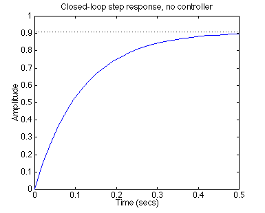
As you can see, our predictions were very good. The system has a rise time of about 2 seconds, is overdamped, and has a steady-state error of about 9%. Now we need to choose a controller that will allow us to meet the design criteria. We choose a PI controller because it will yield zero steady state error for a step input. Also, the PI controller has a zero, which we can place. This gives us additional design flexibility to help us meet our criteria. Recall that a PI controller is given by:
The first thing we need to find is the damping ratio corresponding to a percent overshoot of 40%. Plugging in this value into the equation relating overshoot and damping ratio (or consulting a plot of this relation), we find that the damping ratio corresponding to this overshoot is approximately 0.28. Therefore, our phase margin should be approximately 30 degrees. From our Ts*Wbw vs damping ratio plot, we find that Ts*Wbw ~ 21. We must have a bandwidth frequency greater than or equal to 12 if we want our settling time to be less than 1.75 seconds which meets the design specs.K*(s+a) Gc(s) = ------- s
Now that we know our desired phase margin and bandwidth frequency, we can start our design. Remember that we are looking at the open-loop Bode plots. Therefore, our bandwidth frequency will be the frequency corresponding to a gain of approximately -7 dB.
Let's see how the integrator portion of the PI or affects our response. Change your m-file to look like the following (this adds an integral term but no proportional term):
num = [10];
den = [1.25, 1];
numPI = [1];
denPI = [1 0];
newnum = conv(num,numPI);
newden = conv(den,denPI);
bode(newnum, newden, logspace(0,2))
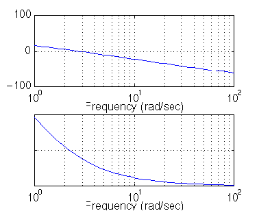
Our phase margin and bandwidth frequency are too small. We will add gain and phase with a zero. Let's place the zero at 1 for now and see what happens. Change your m-file to look like the following:
num = [10];
den = [1.25, 1];
numPI = [1 1];
denPI = [1 0];
newnum = conv(num,numPI);
newden = conv(den,denPI);
bode(newnum, newden, logspace(0,2))
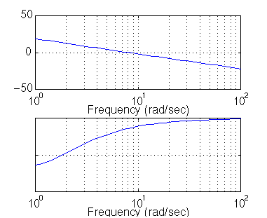
It turns out that the zero at 1 with a unit gain gives us a satisfactory answer. Our phase margin is greater than 60 degrees (even less overshoot than expected) and our bandwidth frequency is approximately 11 rad/s, which will give us a satisfactory response. Although satisfactory, the response is not quite as good as we would like. Therefore, let's try to get a higher bandwidth frequency without changing the phase margin too much. Let's try to increase the gain to 5 and see what happens .This will make the gain shift and the phase will remain the same.
num = [10];
den = [1.25, 1];
numPI = 5*[1 1];
denPI = [1 0];
newnum = conv(num,numPI);
newden = conv(den,denPI);
bode(newnum, newden, logspace(0,2))
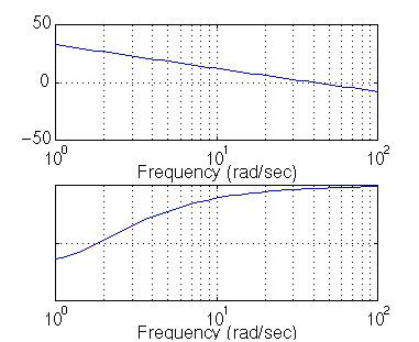
That looks really good. Let's look at our step response and verify our results. Add the following two lines to your m-file:
[clnum,clden] =cloop(newnum,newden,-1);
step(clnum,clden)
As you can see, our response is better than we had hoped for. However, we are not always quite as lucky and usually have to play around with the gain and the position of the poles and/or zeros in order to achieve our design requirements.
This tutorial is continued on the Nyquist page (the link is after the feedback form).


