IMPORTANT: When building the circuit, select resistor values such that the power generated in each resistor in the circuit will be well below its 1/4 Watt power dissipation rating.
METHOD:
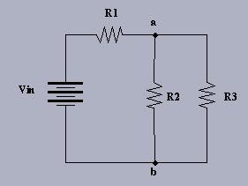
1. Choose appropriate R1, R2, and R3, and measure their values using the DMM.
2. Construct the circuit and adjust Vin=1.0 V (approximately), under load.
3. KVL: Calculate the expected voltages across R1 and R2, and then measure them.
4. KCL: Calculate the expected currents through R1, R2, and R3, and then measure them.
DISCUSSION: