Fall 2017
ENSC 220
ELECTRIC CIRCUITS I
Lab #2: Op Amp
OBJECTIVE:
Using the circuits
below you can study op amps and characterize their behavior.
Comparator
Inverting Amplifier
PREPARATION:
Read Lab Handbook Sections:
2.2.2(c) Using Power Supplies
2.2.4 Function Generator
2.2.5 Oscilloscopes
Appendix X Op-amp configurations.
EQUIPMENT:
Basic lab tools and breadboard (from your supplies)
Dual DC power supply
Digital multimeter (DMM)
Function Generator
Oscilloscope
Operational amplifier (TL072)
Resistors (from open lab stock)
Connecting wire (from open lab stock).
NOTES:
Before connecting the power supply to your circuit,
preset the voltage and then
limit the current to approximately 25 mA.
(Use the techniques outlined in the Lab Handbook Section 2.2.2.)
When making circuit changes, switch off the power supply first.
Turn it on again only after checking the circuit carefully.
Take special care to observe the polarity of the IC (integrated circuit)
power pin connections (as specified in the data sheet for the device).
See Lab Handbook Section 2.3.6(d) 12 Ways to Kill or Wound an IC.
Arrange the components on you breadboard neatly and logically
to facilitate subsequent changes and troubleshooting.
See Lab Handbook Section 2.4.1 Breadboards.
(This section contains valuable info on using your breadboard.)
When operating the op amp from a single supply, us the MASTER section
of the supply, connecting the supply (-) to the (-V) pin of the IC,
and using this connection as the circuit common ground.
Use maximum power supply voltages of +/- 12 volts.
If your op amp circuits ceases to function correctly, consider that:
(a) you may have connected something wrong
(b) a component lead or wire is loose
(c) a short between two or more component leads occurred.
In most cases the op amp is alive and well,
unless you have done something very nasty to it.
If you do damage the op amp, determine exactly what caused the damage
and remedy the fault before replacing the op amp.
Be sure that DC offset on the function generator is set at ``0''.
Check the multimeter setup before connecting it into the circuit.
Improper setup can give incorrect readings and/or damage the meter
or your circuit.
METHOD:
COMPARATOR:
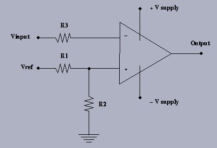
The comparator demonstrates the ``open-loop'' behavior of an op amp.
You can design the reference voltage so that the output voltage will
``switch'' whenever the input voltage (at the inverting input Vn)
reaches the reference voltage Vref.
Remember that the output voltage Vo for an ideal op amp is:
Vo = A(Vp - Vn)
where A -> infinity .
Determine how nearly ``ideal'' your op amp is by the following method:
1.
Choose appropriate R1, R2, and R3 and build the circuit.
2.
Use the function generator to connect a 1 kHz sine wave to the input.
Measure the input and output on the oscilloscope.
3.
Calculate and then measure the switching voltage level.
See what effect there is from putting a resistor (say 2K7)
in series with the inverting input.
4.
Find the meaning of the term ``slew rate'' and measure it.
Slew rate is used to measure how fast an op-amp responds
to the variation of the input signal.
It is measured in Volts /(micro seconds).
5.
Measure the peak-to-peak output swing of the op amp.
6.
Compare this peak-to-peak swing to the supply levels used to power up
the op amp.
7.
Try operating the op amp from a single supply and observe the output.
INVERTING AMPLIFIER:
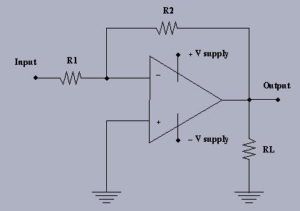
The inverting amplifier demonstrates the ``closed-loop'' operation of an
op amp because a
portion of the output is ``fed back'' to the input. Design the amplifier with a gain of -10 [V/V],
connect a 1 kHz sine wave and use RL = 1K at the output:
1.
Find the maximum amplitude of the input that doesn't distort the output.
2.
Decrease the load RL = 100, and note the effect on the output signal.
3.
See what happens when you operate this circuit
from a single supply (+) and ground.
4.
Return to dual supply.
5.
Set power supply to +/- 12 volt independently.
Vary each side from 12 volts to zero volts, noting the effect on the output.
Restore to +/- 12 volt operation.
6.
Increase the input frequency until the output amplitude decreases by 1/2.
Note the frequency at this point.
7.
Double the gain to -20, measure the 1/2-amplitude frequency again and compare.
8.
Connect the input to ground and measure the output voltage on the 200 mV scale
of the DMM.
DISCUSSION:
All these ``non-ideal'' effects can be explained and analyzed
using a more sophisticated op amp model.
Try to come up with a model to explain some of your observations.
Last modified:
Fri Sep 22 16:37:50 PDT 2017.