Fall 2017
ENSC 220
ELECTRIC CIRCUITS I
Lab #3: RL and RC Circuits
OBJECTIVE:
You will wind (and test) your own inductor, which you will
also use in the AM radio project in a subsequent lab.
You will also investigate the properties of capacitors by making a simple
capacitor and by designing and testing filters and a simple capacitive switch.
PREPARATION:
Read Lab Handbook Sections:
2.3.4 Capacitors
2.3.5 Inductors
Appendix III (p. 280) on standard capacitor values.
EQUIPMENT:
Basic lab tools and breadboard (from your supplies)
Dual DC power supply (Instek GPS-4303)
Digital Multimeter (DMM)
Function Generator (Instek GFG-3015 or equivalent)
Oscilloscope (Tektronix TDS1012 or equivalent)
LRC bridge
Operational amplifier (TL072)
Light emitting diode (general purpose, red)
Resistors (from open lab stock)
Capacitors (47 (or 56) pF, 330 pF, 10 nF, 1000 nF monoceramic, 1 uF)
Connecting wire
Wire and core for inductor
Emery paper
Tape
Materials for ``build-it-yourself''capacitor
NOTES:
Before connecting the power supply to your circuit,
preset the voltage and then
limit the current to approximately 25 mA.
(Use the techniques outlined in the Lab Handbook Section 2.2.2.)
When making circuit changes, switch off the power supply first.
Turn it on again only after checking the circuit carefully.
Take special care to observe the polarity of the IC (integrated circuit)
power pin connections (as specified in the data sheet for the device).
See Lab Handbook Section 2.3.6(d) 12 Ways to Kill or Wound an IC.
Arrange the components on you breadboard neatly and logically
to facilitate subsequent changes and troubleshooting.
See Lab Handbook Section 2.4.1 Breadboards.
(This section contains valuable info on using your breadboard.)
Use maximum power supply voltages of +/- 12 volts.
If your op amp circuits ceases to function correctly, consider that:
(a) you may have connected something wrong
(b) a component lead or wire is loose
(c) a short between two or more component leads occurred.
In most cases the op amp is alive and well,
unless you have done something very nasty to it.
If you do damage the op amp, determine exactly what caused the damage
and remedy the fault before replacing the op amp.
When operating the op amp from a single supply, us the MASTER section
of the supply, connecting the supply (-) to the (-V) pin of the IC,
and using this connection as the circuit common ground.
Check the multimeter setup before connecting it into the circuit.
Improper setup can give incorrect readings and/or damage the meter
or your circuit.
When operating the op amp from a single supply, us the MASTER section
of the supply, connecting the supply (-) to the (-V) pin of the IC,
and using this connection as the circuit common ground.
Be sure that DC offset on the function generator is set at "0".
Wind your inductor turns tightly together, taking care ti avoid ``pig-tails.''
Use tape to secure taps and ends of windings on your inductor.
See Lab Handbook Section 2.3.5(f) Winding Inductors.
After sanding the insulating varnish off the taps and lead-ends on your inductor,
and inspecting them carefully to ensure that all insulation is gone,
you may need to tin them using solder and a soldering iron.
See Lab Handbook Section 2.4.2 An Introduction to Soldering.
Note that this cannot be done with the continuously variable inductor,
because turns could be shorted by solder.
METHOD:
INDUCTOR:
1. Construction the inductor.
The inductance L of an air-core inductor is approximated by:
L = (d^2 n^2)/(18d + 40l)
where:
L = inductance (measured in uH)
d = coil diameter (inches)
l = coil length (inches)
n = number of turns.
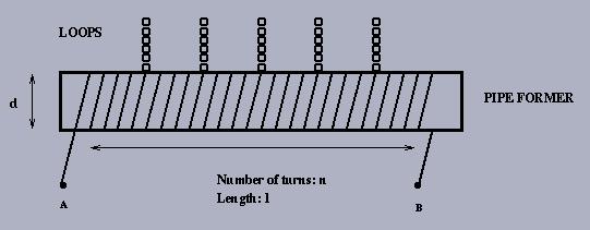
You will be supplied with #26 AWG enameled wire (0.0170" diameter) and a
5" piece of nominal 3/4" (actual O.D.1-1/16") plastic pipe to construct your
inductor (you should not need any more than 30' of wire). You will probably
want to experiment with inductances in the range of 50 - 200 uH when you
finally build your AM radio. You can build a "tapped" inductor by inserting a
twisted wire loop "tap" at several sites along the inductor length:
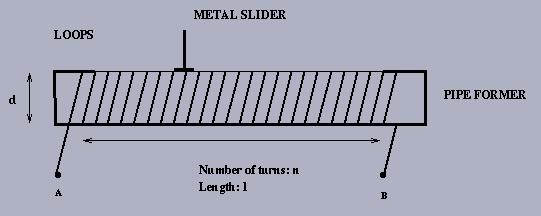
Alternatively, you can build a "variable" inductor by winding the inductor,
then use a piece of emery cloth (or fine sand paper) and lightly sand off
the enamel wire coating. Then run a metal "slider" across the exposed
windings to set up a variable tap:
2.
Use the LRC bridge to measure your total inductance and that of each tap.
Compare to calculation.
3.
Also devise your own method to measure the total inductance (e.g., based on
a step-response technique) using the terminal characteristic for an inductor:
v = L di/dt . Compare to calculation.
CAPACITOR:
1. Use a sample capacitor from the Lab.
2.
Measure the capacitance of the capacitor using the LRC bridge.
3.
Also devise your own method (e.g., based on a step-response technique)
using the terminal characteristic for a capacitor: i = C dv/dt.
HIGH PASS FILTER:
1.
Construct a simple RC high pass filter circuit, using your capacitor.
2.
With input level constant, sweep the input over a wide range of frequency
(sine wave), and plot the output level response.
3.
Repeat above using a capacitor of, say, 330 to 1000 nF instead of your
capacitor.
4.
Repeat using a capacitor of, say, 15 to 100 pF instead of your capacitor.
LOW PASS FILTER:
1.
Construct a simple RC low pass filter circuit, using your capacitor.
2.
With input level constant, sweep the input over a wide range of frequency
(sine wave), and plot the output level response.
3.
Repeat above using a capacitor of, say, 330 to 1000 nF instead of your
capacitor.
4.
Repeat using a capacitor of, say, 15 to 100 pF instead of your capacitor.
CAPACITIVE SWITCH:
1.
Use your capacitor (along with an op amp(s) circuit) to produce a simple
capacitive switch. The switch should be designed to operate as follows:
2.
Pressing on the capacitive element should alter its capacitance.
Explain how.
3.
Assuming a sinusoidal input, devise a circuit whose output amplitude
depends on C. Experiment with different frequencies from 10 kHz - 1 MHz,
and possibly with the R and C in your circuit, to obtain a maximum change
in output level when your capacitor is pressed. If possible, try to get at
least a 1.5x to 2x level change.
4.
Measure the change in this output using a simple comparator circuit.
5.
Process the output of this comparator so that you get a DC signal that goes up
and down as you press on your capacitor. This can be done by choosing and
setting an appropriate reference voltage on the comparator.
6.
The comparator output should ``switch'' on an LED wired in series with
a current limiting resistor as shown below.
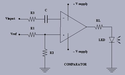
The resistor RL inserted between the comparator output and the LED is
used to limit the current through the LED.
See Lab Handbook Section 2.3.7(a) LED.
Refer to ``Testing an LED'' for information on lead identification.
You can try several resistors to adjust the intensity to your liking. The
LED conducts current in one direction only (in the direction of the arrow)
so you may have to reverse the LED connections if it does not light the
first time.
If you want to read more about diodes (the device you are using is a Light
Emitting Diode - LED) then you can refer to Chapter 6.
Your lab write-up should investigate a number of considerations
(design, analysis, measurements, observations, testing, calibration, etc.)
for all these experiments.
Last modified:
Fri Sep 22 16:37:50 PDT 2017.