METHOD:
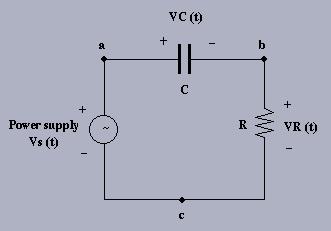
1. Build the above circuit on your breadboard, using R = 1K5 and C=0.1 micro F.
2. Connect CH1 of the scope to node ``a'' (with the probe ground connected to ``c''). Adjust the time and voltage sensitivity (time/div and volts/div scales) to display at least one cycle of VS(t) and the maximum amplitude. Measure the amplitude and period of VS(t) using the time/voltage sensitivity indicators. Use p-p AUTO, AUTO or AUTO LEVEL triggering mode with INTernal source CH1. Set the function generator to produce a 1KHz sinusoid signal with 1.0 V peak ampltiude and connect it to the circuit. Change to NORMal triggering mode and experiment with the triggering level and slope controls.
3. Connect CH2 of the scope to ``b'' and measure the amplitude and phase (relative to CH1) of the signal VR(t). Sketch the waveforms VS(t) and VR(t) below as accurately as possible.
4. Connect CH2 of the scope to ``c'' and move the ground of CH1 (and CH2) to node ``b''. See Lab Handbook, section 2.2.5b on oscilloscope grounds. Invert CH2 and measure the amplitude and phase of VC(t) (CH1) relative to VR(t) (CH2) and sketch VC(t) below as well.

5. Verify that VR(t) leads VC(t) by 90 DEGREES. Turn the time sensitivity CCW to X-Y mode and you should see a plot of VC(t) vs. VR(t). This displays the V-I relationship for the capacitor with an applied sinusoidal voltage. Experiment with different frequencies and note how the display changes in terms of phase and amplitude relationships. Work through the circuit analysis below and convince yourself that the expected results match those you observe.
ANALYSIS:
You can derive expressions for the voltages and current in this circuit using
KVL and the
governing equation for a capacitor. Since the source input VS is sinusoidal,
and the circuit is
linear, all currents and voltages in the circuit are also sinusoidal with the
same frequency as the input:
Click here for the DERIVATION of the voltage waveforms.
Verify the amplitude and phase of these signals at 1 kHz to convince yourself that this analysis is correct.
DISCUSSION:
The objective of any experiment is to verify a set of expected results
within a specified range of certainty.
We perform measurements of frequency, amplitude and phase in this experiment.
What is the uncertainty associated with each of these measurements using
the OS (assume the OS is perfectly calibrated - estimate the highest
resolution you can guarantee from the screen)?
Once you have this information you can calculate how these errors propagate
through the equations above to provide you with a range of uncertainty
in the measured quantities of interest (namely amplitude and phase).
See how close your measurements coincide with the expected values.
Another test you can perform is the so-called ``black box test.'' See if you can work backwards from your measurements to calculate values for R and C. Then see how closely these values match those obtained from the LRC bridge.
See Lab Handbook Sections 2.3.3 (Resistors and Resistive Devices) and 2.3.4 (Capacitors).
Last modified: Fri Sep 22 16:37:50 PDT 2017.