METHOD:
TIME-DOMAIN RESPONSE:
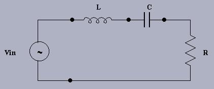
Use one capacitor (suggest C = 100 pF - 10 nF) and two different inductors: the one that you made for Lab #3 and a 100 uH inductor (supplied to you in your parts kit). Try to calibrate your inductor close to 100 uH for comparison purposes. Use two different resistors: one that demonstrates under-damping (Runder) and one producing an over-damped response (Rover). Sketch the step response for the output voltage Vout taken across the resistor, R, in each case. Measure (if possible): overshoot, rise time, settling time, and frequency of oscillation.
Click here for the DERIVATION of the natural frequencies.
FREQUENCY-DOMAIN RESPONSE:
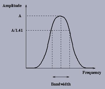
Apply a sinusoidal voltage to the input. Choose several appropriate frequencies and measure the amplitude (with respect to the input amplitude) ratio and phase difference (with respect to the input sinusoid) at each frequency. Plot the frequency response (amplitude vs. frequency) for each case (Runder and Rover) as shown in the figure.
For both Runder and Rover cases,
determine from these plots:
1. Resonant frequency (wr)
2. Bandwidth (BW)
3. Quality factor (Q, where Q = wr/BW).
Note that a ``high Q'' circuit has a
very narrow bandwidth with respect to its resonant frequency.
DISCUSSION:
For both Runder and Rover cases, calculate:
1. Resonant frequency: wr = 1/sqrt(LC)
2. Bandwidth: BW = R/L
3. Quality factor: Q = sqrt(L/C)/R.
Compare these to the values determined from your graphs.
If a series RC, RL, or RLC circuit was given to you in a black box (with access only to the two input terminals) how could you determine the component values? Try to identify several circuits.
Last modified: Fri Sep 22 16:37:50 PDT 2017.